Software Architecture
Introduction

Software Communication Architecture
Detector
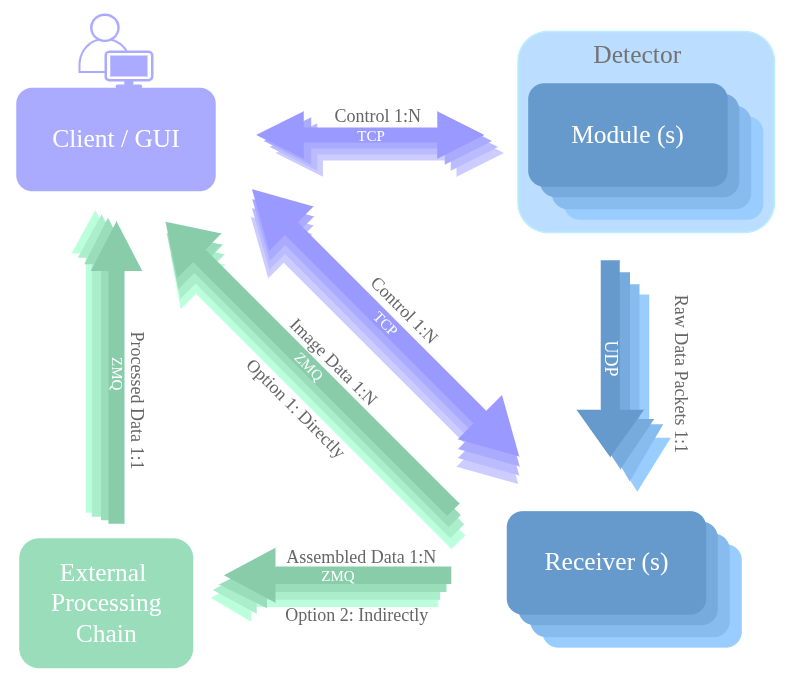
A detector can consist of a single module or multiple modules combined.
Module
Each module sends its data via UDP over distinct ports. Since UDP does not provide acknowledgements, data is transmitted as fast as possible, which can lead to packet loss if the network is not properly configured, among other causes. A single image streamed out could be split into multiple UDP packets and each module can have one or two UDP ports to transmit in parallel different physical sections of the image.
Receiver
UDP data is received by one or more receivers—either built-in or custom. In the diagram above, there is one built-in receiver per module (1:1). For example, a detector with two modules (two hostnames) will have two built-in receivers. Each receiver could listen to one or two UDP ports (depending on the module it listens to). For each UDP port, the receiver reassembles these packets into sub-images and optionally saved to file.
ZMQ
Each UDP port in the receiver can also stream out independently sub-images via ZMQ (core: TCP/IP).
Directly to the GUI for display.
To an external processing chain for post-processing and optional storage, which can in turn stream the processed data back to the GUI.
Client
A single client can configure and control individual modules and receivers, or multiple of them in parallel. This communication is handled over TCP/IP, ensuring acknowledgements.
It can also listen to multiple ZMQ sockets from the Receiver(s) or the external processing chain to assemble the full image for GUI display or Client call backs.
Next, each component is examined in detail.
Module

Module Architecture
Detector Server
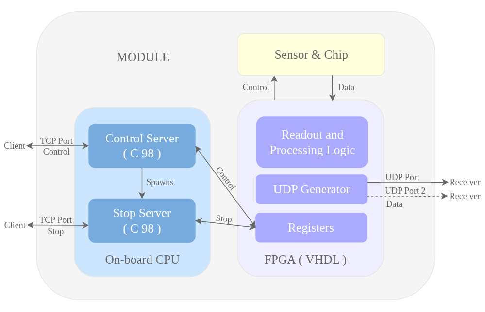
The module contains an onboard CPU (type depends on the detector — e.g., Nios for Mythen3, Blackfin for Jungfrau). The detector server and detector configuration files are stored here, with the server compiled in C using the CPU-specific compiler. Running the binary starts a Control Server and a Stop Server. Client control/configuration requests go to the Control Server via the TCP control port, while stop/status requests go to the Stop Server via the TCP stop port as the Control Server may be busy with an acquisition. For more details see detector server and detector simulators to play around with.
Firmware
The module also includes an FPGA with VHDL firmware (file format depends on the detector — e.g., Mythen3 uses .rbf, Jungfrau uses .pof). Client requests trigger register read/write operations in the FPGA, which manages chip readout and processing. Data from the chips is sent through a UDP generator in the FPGA and output as UDP packets via the UDP port. A single image may be split across multiple packets. A module could have 1 or 2 UDP ports to transmit in parallel different physical sections of the image.
Upgrade

Software Upgrade Components
There are mainly three components to the soft upgrade:
Detector Server upgrade: The server running on the module.
Firmware upgrade: The VHDL code running on the FPGA.
slsDetectorPackage upgrade: The client code running on the host PC to control the module(s) and receiver(s) if any.
Please use the update command when updating both the server and firmware simulataneously and programfpga command when only updating the firmware. See firmware upgrade for details.
When only updating the detector server, use the updatedetectorserver command command. See detector server upgrade for details.
Note
Compatibility
When updating anything on the module via the client (server or firmware), the server and client will have to be compatible (same major version). If not, the client and server will not communicate properly.
Since they are ideally compatible before the upgrade, upgrade the server and firmware first, then the slsDetectorPackage.
Receiver

Receiver Architecture
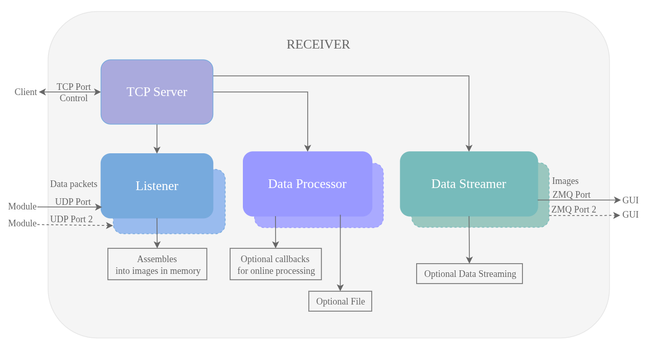
The receiver mainly consists of:
A TCP server that listens to client TCP requests for configuration and control.
One or 2 listeners that listen to a UDP port each, reassembling the UDP packets into sub-images in memory.
One or 2 data processors that processes the sub-images with optional callbacks for online processing and file writing.
One or 2 data streamers that stream the processed sub-images to the GUI or external processing chain via ZMQ.
Few characteristics of the receiver:
It can be run on the same host as the client or on a different host.
There is a receiver process for every module and a file for every UDP port.
Each receiver process is independent and asynchronized for performance. So are the UDP ports.
Client

Client Architecture
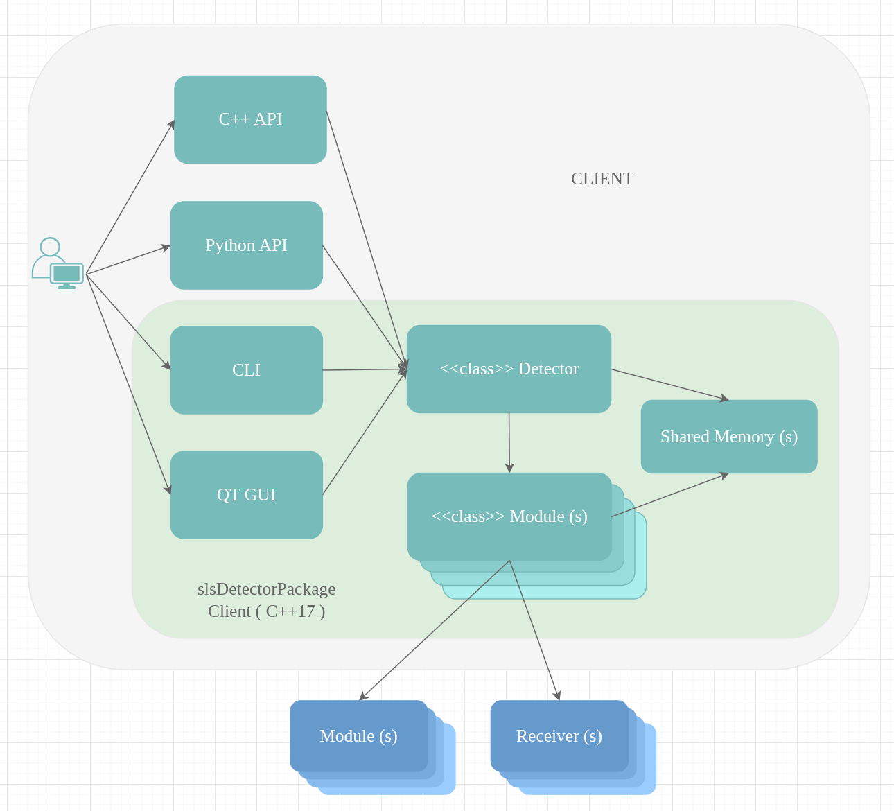
Users can control the detector and receivers through four interfaces:
their C++ API,
their Python API,
the command-line interface, or
the Qt-based GUI.
Regardless of the interface, each ultimately invokes our Detector class—either directly (CLI and GUI) or through our C++/Python libraries (when using their APIs). The Detector class then calls the appropriate module functions, either for a specific module or in parallel for all modules. Each module object sends requests over TCP to its corresponding module and, if needed, to the receiver.
Shared Memory
As the command-line interface is supported, shared memory is used to store essential information such as the module hostname and TCP port, or the receiver hostname and TCP port. This ensures the system knows which components to communicate with, without requiring the user to re-enter this information for every command-line call.
Note
Only the client maintains shared memory. Care must be taken when multiple users operate from the same PC. See multi detector and user section for more details.